Selecting the Airport Glide Range overlay displays a theoretical representation of your aircraft’s glide envelope (using the glide data provided within the aircraft model). It has two different functions, depending on if you are planning or flying.
Aircraft glide envelope
This green dynamic shape takes into consideration aircraft glide ratio, wind and terrain to derive and display an area that your aircraft could theoretically reach in at a manoeuvring height of 1500 feet AGL – if placed into a glide at this very moment.
From the current location, the current Altitude Above Ground Level (AGL), the winds for the given location, the altitude and the glide performance characteristics of the aircraft – we simulate the glide performance of the aircraft in a 360-degree radial around the aircraft to produce the glide envelope. The glide range for a given radial is from the location/altitude of the aircraft to a point along the radial where the aircraft reaches 1500 ft. AGL or comes to with-in 500 ft. of terrain (a hill, mountain or obstacle) between the aircraft and the airfield.
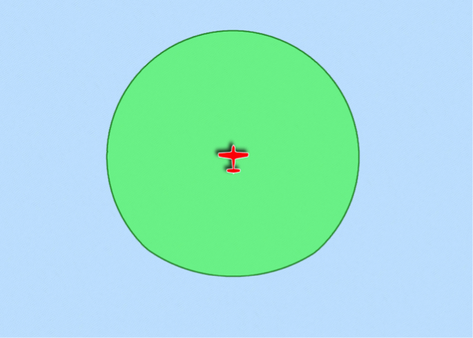 Glide envelope - nil wind/nil terrain example
This shape will change as you fly around and over various types terrain. In zero wind, with no terrain undulations (such as a large body of water), the glide envelope will appear to be near circular. If however, you are over land and during the glide the aircraft would not clear terrain by a minimum of five hundred feet AGL the envelope will be reduced in size and shape accordingly.
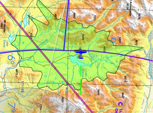 Glide envelope - low altitude, high terrain example
The example above shows an aircraft flying at a low level over mountainous terrain and the associated aircraft glide envelope. Note the edges of the glide envelope follow the contours of the surrounding terrain (i.e. the point at which the aircraft would come to with-in 500 ft. of the terrain).
The glide area behind the aircraft is derived via an algorithm that assumes a height loss of 500 feet during the turn to face that new direction.
Forecast wind effects are taken in to account by the simulation. Strong enough winds will cause the envelope to be displaced (i.e. the aircraft will no longer be in the centre of the envelope), owing to the degraded glide distance over ground with a headwind versus a tailwind (or part thereof).
Note that this is an aid to situational awareness only – it does not take into account aircraft configuration, localised wind phenomena, or changes during the glide.
Airport glide envelope & PSEA (formerly ASETPA) planning (Plus/Premium feature)
When the Airport Glide Range overlay is selected, grey areas surrounding airports appear along your planned route. The shapes of these will be affected by the same parameters (wind, terrain, etc) as the Aircraft Glide Envelope, however each of the theoretical simulations are completed using the Lat/Long of the airport, and a desired manoeuvring height of 1500 feet above airport elevation. These could be considered catchment areas for each airport at your planned cruise altitude. Only airports that meet the Shortest Runway Length criteria in the selected aircraft profile will be displayed.
Essentially, when at planned cruise altitude, if your aircraft is flying within a grey envelope (or if the green and grey envelopes merge over an airport), a safe glide to that place is theoretically possible.
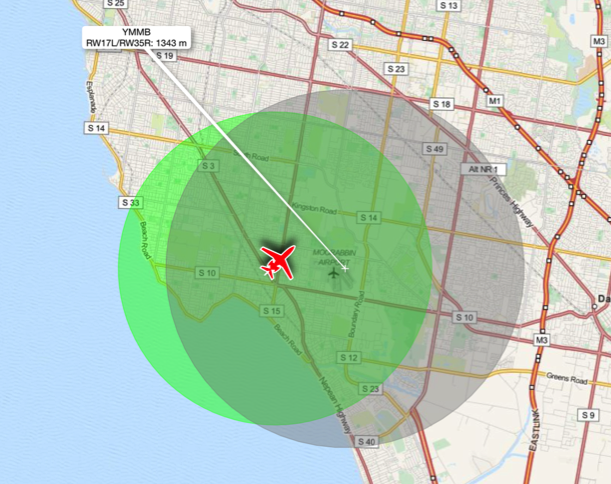 Airfield and aircraft glide envelope overlap
Note that in the above example, the glide envelope is almost circular due to little wind or terrain influence.
Maximizing glide during flight planning
Displaying the glide envelopes within range or almost within range of a proposed flight path allows the pilot to maximize in-flight safety from a glide perspective. In the following screen capture the proposed flight plan from YMMB to YSBK has been modified to maximize the period of flight within glide range of an airfield.
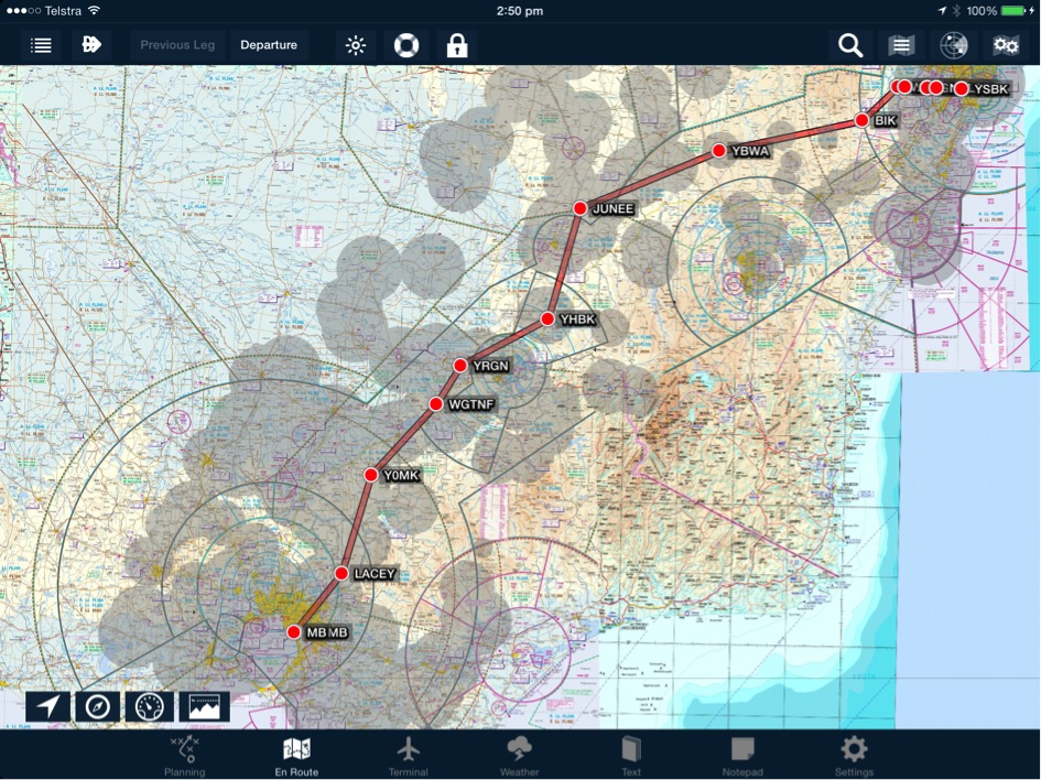 Maximizing glide during flight planning
Areas with many suitable airports within a relatively small area will have merging glide envelopes. Theoretically, when the aircraft position is within a grey area, a safe glide to around 1500’ above a suitable airport is possible (see below).
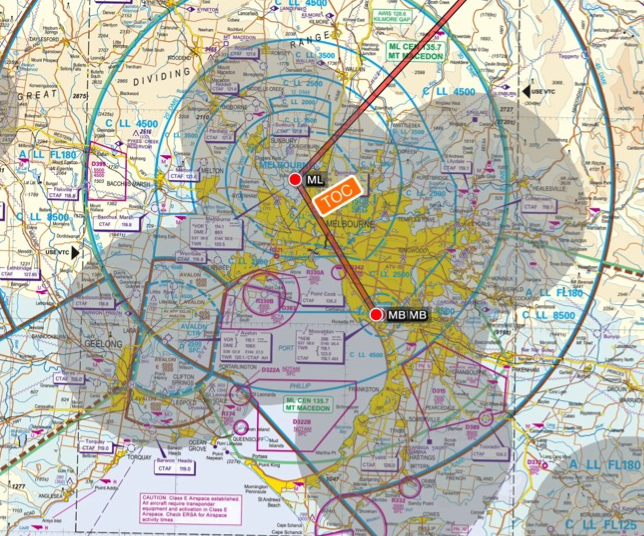 Merged airport glide envelope example
Dynamically calculating closest airfield in flight
While in flight, AvPlan will calculate and designate the most appropriate and/or the closest airfield for the parameters set within the aircraft profile (glide ratio & minimum required runway length). An algorithm constantly prioritizes, selects and labels these using the following criteria (in order of preference):
- Airfields within current glide range and with suitable runways. Suitable runway in this sense means that the one or more runways are long enough for the aircraft to land. Given that airfields may be equidistant from the aircraft’s location or that the runway lengths for one may be longer than the other(s), a weighted scoring mechanism based on distance and runway length is used to determine the best airfield based on this algorithm. This selection is denoted by black text within the airport label.
- Airfields within the current glide range with maximum runway length that is less than the minimum runway length requirement for the aircraft. In this instance the algorithm selects the best airfield based on the shortest glide distance. This selection is denoted by violet text within the airport label.
- Airfield within the current glide range with unknown runway length. In this instance the algorithm selects the airfield based on the shortest glide distance. This selection is denoted by blue text within the airport label.
- Airfield outside the current glide range with unknown runway length. In this instance the algorithm selects the airfield with the shortest glide distance. This selection is denoted by red text within the airport label.
Need more help with this?
Help Centre (Tap and hold to open the Link)


