Longitudinal (forward-aft)
The first part of this section deals with normal Longitudinal weight and balance envelopes used by all aircraft. The additional complication of Lateral weight and balance required for helicopters is also addressed in AvPlan if the aircraft type requires it.
Creating the envelope
AvPlan Uses Weight and Arm Values.
AvPlan EFB uses two pieces of data for each corner, a weight and arm (length), to build the envelope.
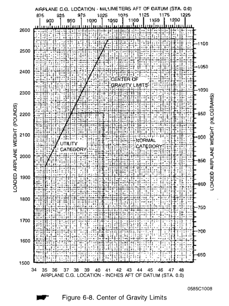
From your POH, use this type of graph (from a C172):
- Tap Settings > Aircraft Type Database > [your type] > Weight and Balance.
- Tap the Edit button in the top-right corner of the screen. You should see green plus signs appear down the left side of the window.
- Tap a green plus to add a corner. This will form Corner 1. It doesn’t matter what corner you start in, AvPlan always moves clockwise around the envelope. However, it’s always a good idea to start in the bottom-left of the envelope.
- You’ll need the weight and the arm. In the above example (figure 6-8), Corner 1 would be 35 inches at 1500 lbs. Note that you can set the weight and arm units on the Basic Details page of your aircraft profile.
- Tap the back button to return to the list. There should now be one entry.
- Tap the green plus, and add Corner 2’s details. In the above case, it’ll be 35 inches at 1950 lbs.
Corner 3 will be 41 inches at 2550 lbs. - Continue around the envelope until the complete shape is created. The amount of corners will depend on the structure of the shape. In the above C172 example, there are five corners required. (note, there is no need to create Corner 1 twice)
It may look slightly different as the scale of the graph may differ to the one in the POH. This doesn’t mean the graph is incorrect, as long as the relative shape is correct.
Your envelope will typically look like a plain (or truncated) rectangle
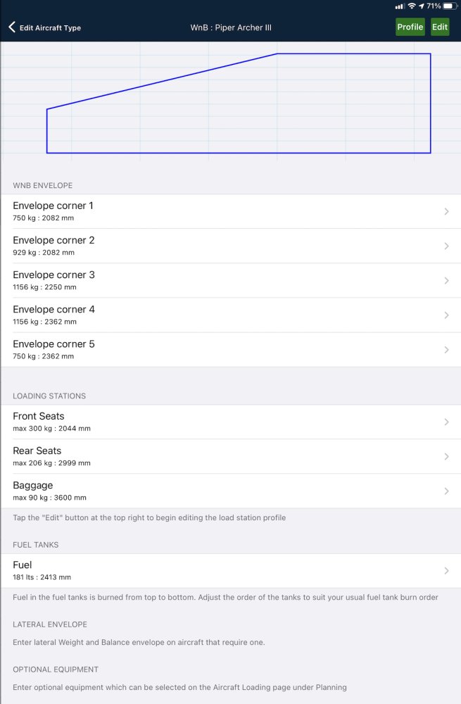
The correctly completed envelope shown below is constructed for a PA28 Archer in exactly the same way as described above.
 Completed PA28 Envelope
If you wish to also add the Utility Category envelope to the display, continue around the envelope for a second time, but with the corners associated with the reduced limits. You’ll end up with around 10 corners.
Some POHs do not explicitly show the envelope
Sometimes, a graph is not provided by the manufacturer in the POH, so the envelope needs to be created from a word picture. These are usually found somewhere in the Limitations section.
Consider this scenario:

You’ll also need to know the MTOW, which will give you half the corner details.

So, the only other information you need to obtain is the empty weight of the aircraft. For the purposes of the example, we will use 306 kg.
Corner 1 will be 1860 mm at 300 kg. (a weight just below the empty weight)
Corner 2 will be 1860 mm at 599 kg. (MTOW)
Corner 3 will be 2040 mm at 599 kg
Corner 4 will be 2040 mm at 300 kg.
This will create a rectangular envelope, which most two-seat wet-wing GA aircraft have.
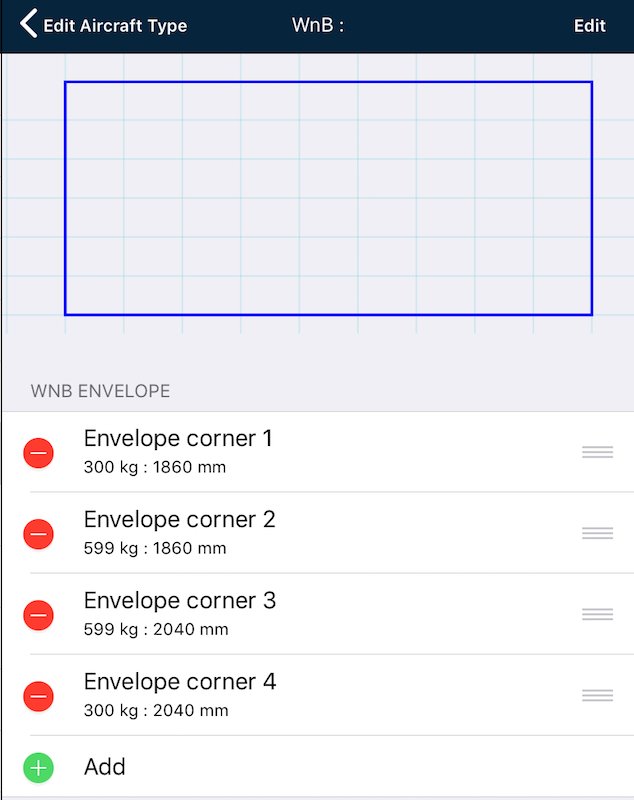 Completed envelope
If the shape is completely different, something is wrong: have you used moments instead of arms?
AvPlan does not use Moment values.
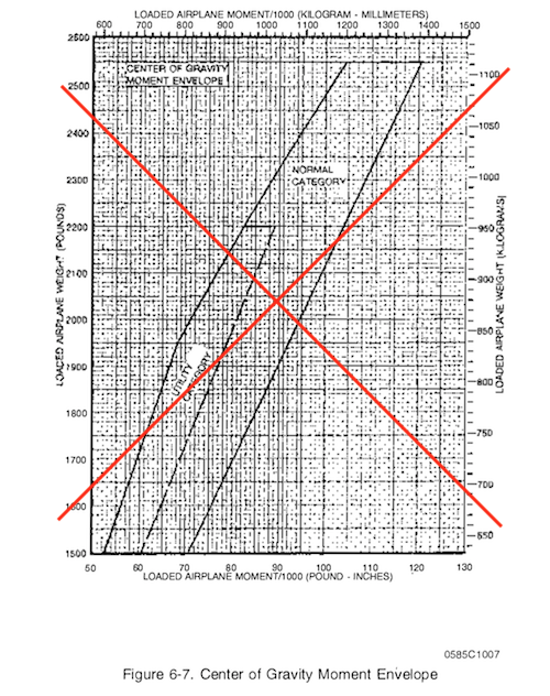
If your POH describes the CofG envelope in terms of weights and moments, then you must convert the moments to arms.
Recall that moment = weight x arm, so take the moment values and divide by the corresponding weights to get the arm values.
A further complication is that moment values are often (correctly) very large numbers. To make these large numbers more manageable, moment-envelopes are frequently published in terms of Index Units (IU). Index Units are just moments divided by a scale-factor (100, 1000, 10000 are common scale-factor values). If you have to deal with IU’s just divide by the corresponding weights and multiply by the scale factor to get back to arm values.
Adding load stations
Load stations are added in a similar way to envelope corners. Tap the Edit button in the top-right to reveal an Add button.
At a minimum, each station requires the Load Station Name and Load Station Arm to be entered.
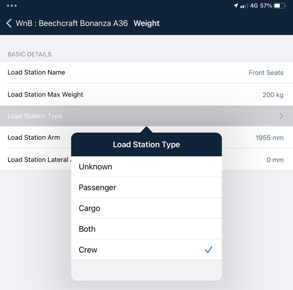
The Load station max weight is optional, as not all stations have a promulgated maximum weight. Mostly, this will be used for cargo/baggage storage locations with a placarded maximum weight. In the Aircraft loading / weight and balance / fuel planning page, if a weight is entered higher than the station’s maximum weight the row’s text will turn red.
The Load Station
The Load Station Type defaults to “unknown” if not specified otherwise, which effectively means that the load station can be either pax or cargo (or indeed both), but will default to cargo unless the Aircraft Loading/ Weight and Balance / Fuel Plan section in a flight plan usining this aircraft type specifies otherwise .
- For a baggage area, the Load Station Type should always be “Cargo”.
- For Crew Seats, it is recommended to use “Crew”
- For passenger seats, select either “Pax” or “Both” (i.e. pax and/or cargo) according to your intended use.
Load Station Lateral Arm can be left blank, unless the aircraft is a helicopter with lateral arm values presented for the load station in the POH
Adding Fuel tanks
Fuel tanks are added below the FUEL TANKS subheading.
Add a row. You’ll need to name the row, set the maximum capacity and provide the fuel tank’s arm figure.
 Fuel tank entry example
Note, in the above example that L and R wing tanks have been combined into one entry. If you have a second fuel tank with a different arm, add a second (or more) row.
Advanced fuel tank arms can also be added. These allow different moment arms for different fuel levels (e.g. for swept-wing aircraft, or those with an unusually-shaped fuel tank system). Moment arms are linearly interpolated between values in the table. Only use this option if you are given an advanced fuel burn arm table in the POH.
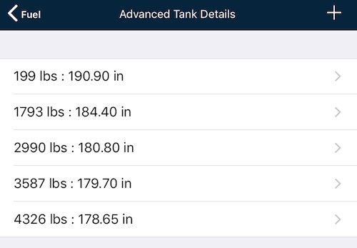 Advanced tank example
Usable Fuel vs Unusable Fuel
Only Usable fuel quantities should be included in tank capacity values. Unusable Fuel should not be included in tank capacity values. The weight associated with unusable fuel is included in an aircraft’s Basic Empty Weight.
Need more help with this?
Help Centre (Tap and hold to open the Link)


